1995 Wood Frame Construction Manual for One- and Two-family Dwellings
![]() Open access peer-reviewed chapter
Open access peer-reviewed chapter
Structural Design of a Typical American Wood-Framed Unmarried-Family Home
Submitted: September 19th, 2018 Reviewed: March 18th, 2019 Published: May 11th, 2019
DOI: 10.5772/intechopen.85929

IntechOpen Downloads
2,326
Total Chapter Downloads on intechopen.com
Abstract
Lite-woods framing structure techniques have been traditionally used in America for the construction of single-family residences. Dimensional forest lumber is readily available and due to its user-friendly unit of measurement dimension tin exist packaged neatly and transported to work sites by either commercial transport or personal vehicle. The unit pieces of dimensional lumber are light and hands handled once on the work site. Blueprint of low-cal-framed single-family homes is typically conducted by an architect or construction contractor using prescriptive edifice codes. A structural engineer can help, if needed, with pattern items not within the telescopic of the building code or if alternative design approaches are required. An possessor may cull to involve the engineer to amend quality or economy of the home design. Engineers typically become involved with design items such as foundation design, steel framing design, or engineered product specification. In this chapter, the blueprint of a typical light-framed home is discussed. The main structural assemblies are described and subsequently designed using a combination of prescriptive guidance and engineering design.
Keywords
- residential
- single-family home
- wood
- light-framing
- business firm
*Address all correspondence to: memari@engr.psu.edu
1. Introduction
The prevailing system used for the construction of single-family homes in the Us is platform framing using calorie-free wooden dimensional lumber. Structural assemblies such as the roof, floors, and walls are generally constructed with nominal l.8 mm (2 inch) lumber members ranging in nominal depths from 101.6 to 304.8 mm (4–12 inches) and sheathed with structural wood panels for stability and security, such every bit oriented strand board (OSB) or plywood.
Wood structural materials are preferred by US homebuilders largely because (1) the US home building industry is mostly familiar with wood framing method, (two) the units of construction (i.e., studs, joists, panels, etc.) are small and easily transportable, and (3) forest-framed structures can be erected without the need for specialized tools or large equipment.
In this chapter, the complete process of designing a typical US residential dwelling using wood-frame systems will be illustrated. The typical US pattern methodology and basis will be used to accomplish the designs. The International Residential Code (IRC) [ane] is the blueprint footing used by most government to regulate the design and structure of single-family residences. The post-obit major aspects are discussed in this chapter:
-
Provide introductory cloth such as the description of the home to exist designed, applicable design codes, and external loading assessment for residential structures.
-
Design the home using a woods-framed platform system. The load path will be discussed likewise every bit specific design codes relating to wood-framed structures. The outcome of specifying and detailing typical structural elements of the home will be specified and details provided.
The scope is limited to the structural design and performance of i single-family residential dwelling. The load-bearing wall systems are the primary components of the building enclosure, and the structural properties of the wall organization are only one of many considerations that must exist taken into business relationship. While cladding compatibility, thermal functioning or the hygrothermal characteristics of a wall organization are very of import, such aspects are not the focus of this report and will not be discussed.
The home design considered in this study is a two-story regular-shaped home with a basement and attached two-car garage. The floor plan was provided by S&A Homes, which is a midsized homebuilder that builds homes and provides architectural design services to customers in Pennsylvania and West Virginia. The flooring plans and drawings for 1 of their standard habitation packages are provided in the Appendix. Clients of S&A Homes tin select this floor plan from an array of flooring plans and make slight variations to it if desired. S&A Homes will then design, detail, and construct the habitation for the client on the chosen lot, typically one of Southward&A'due south own residential developments.
The home program/fashion shown in the Appendix is a popular model in S&A'due south territory and is representative of the size and fashion of homes desired by the average homebuyer of this decade. The habitation consists of nearly 214 one thousand2 (2300 fttwo) of finished floor area with the basement bachelor for finishing if then desired by the prospective homeowner. The flooring plan has features typically seen in modernistic homes. The starting time floor contains a large kitchen open up to the family unit room with admission to both the dining room and the fastened ii-auto garage. The 2d floor has four bedrooms with the master suite containing its own large bathroom as well as a sitting area and walk-in closet (WIC).
Advertisement
2. Applicable codes and standards
The IRC is the prevailing design lawmaking used for the construction of 1- or two-family dwellings in the USA. The 2015 IRC [ane] is the current adopted code in the Country College, PA area, and will exist used as the governing blueprint code for this report. In order to construct a single-family dwelling, the homebuilder must first apply to the local code office for a building permit. It is necessary to provide a complete architectural plan set detailing how the builder intends to comply with the requirements of the IRC, along with several other items such as the manual J [ii] heat loss-gain calculations for the construction and selection of free energy compliance path. The IRC largely provides a prescriptive basis for dwelling house design and in many instances is adequate for single-family domicile design. The envelope and structural components are typically selected past the architect, builder, or homeowner from pattern tables within the code. If prefabricated engineered components such as I-joists, laminated veneer lumber (LVL) components, or roof trusses are used in pattern, a structural engineer is required to review their specification and application.
This is typically the extent of a structural engineer's involvement in residential design other than specialized situations non covered by the IRC and occasionally foundation pattern. If engineered design is necessary in conjunction with the prescriptive standards, then compliance with the 2015 International Building Code (IBC) [iii] requirements for those portions of the design is required. Engineers will bear their analysis based on requirement set forth in the IRC, IBC if necessary, and ASCE seven-10 minimum design loads for buildings and other structures (ASCE 7) [4] [ASCE stands for American Lodge of Civil Engineers]. The IRC and IBC also let designers to refer to the 2015 AWC
Advert
3. External load conclusion and serviceability requirements
This study will focus on the appropriate residential structural building loads for the State College, PA expanse, for an example design case. The designs will include only the effects of dead loading, floor alive loading, roof alive loading, snow loading, and current of air loading. Residential structures in ordinary situations are designed to resist both gravity loads and lateral loads. External loading for homes is prescribed in either Chapter iii of the 2015 IRC or in ASCE 7. ASCE 7 is the standard referenced in the 2015 IRC, and therefore this version will be referenced in this report. Both the IRC and the ASCE 7 will be used to develop the external loads for this study. In addition to the external loads, the serviceability criteria must also be considered. For this design, only alive load deflection limits volition be considered.
3.1 Gravity loads
The gravity loads are those loads that deed in the direction of gravity. The gravity loads of importance for residential structures are dead load (DL), floor live load (50Fifty), roof live load (RL), and snow load (Southward50).
3.2 Dead load (DL)
Dead load is the load that is permanently and continuously applied to a structure. Typically, dead load refers to the self-weight of the material used in construction or a load that is applied in a permanent nature such as a known location of a slice of heavy equipment or a large isle in the kitchen. Unless noted otherwise, the Due south&A Homes expressionless load criteria will exist used for the woods-framed pattern of this home. These loads are typical for residential design and were largely derived from ASCE vii Table C3-1. Dead loads are listed in Tables 1, 2, iii.
| Sub-component | Weight N/m2 (lbf/ft2) |
|---|---|
| Carpet/vinyl | 47.ix (1.0)a |
| xix.ane mm (¾ in) plywood | 114.9 (2.4) |
| 301.6 mm (11 vii/viii in) I-joistsb | 91.0 (1.9) |
| Mechanical allowance | 95.8 (ii.0) |
| 12.7 mm (½ in) gypsum ceiling | 105.three (two.2) |
| Total | ≈454.9 (10) |
Tabular array 1.
Floor/ceiling assembly weight.
For flooring areas known to have ceramic tile flooring covering, increase load to 0.96 kN/mii (20 lbf/ft2).
Weight is derived from Weyerhaeuser publication #TJ-4000 for 230 or 360 series joists.
| Sub-component | Weight N/k2 (lbf/ft2) |
|---|---|
| Truss framing | 95.8 (2.0) |
| xi.one mm (7/sixteen in) sheathing | 81.4 (one.7) |
| Asphalt shingles | 114.nine (2.4) |
| 228.six mm 9 in insulation | 86.2 (1.8) |
| 12.7 mm (½ in) gypsum lath | 105.iii (2.2) |
| Miscellaneous | 95.8 (2.0) |
| Total | ≈ 579.iv (12) |
Table 2.
Roof associates weight.a
Engineered wood truss roof system.
| Sub-component | Weight |
|---|---|
| Exterior wall assemblya | 526.7 N/mtwo (11.0 lbf/fttwo) |
| Interior wall assemblyb | 383.0 N/gii (8.0 lbf/ft2) |
| Patently concrete | 22.8 kN/1000three (145 lbf/ft3) |
| Reinforced physical | 23.6 kN/m3 (150 lbf/ft3) |
Table 3.
Miscellaneous materials.
two × half dozen woods studs at 406.4 mm (16 inch) O.C. with 12.7 mm (½ inch) gypsum wallboard and vinyl siding.
Wood or steel studs with 12.7 mm (½ inch) gypsum wallboard on each side.
3.3 Live load
Live loading is a gravity loading that is temporary or intermittent in nature. The three live loads considered for the pattern of this dwelling house are floor live (50L), roof live (RL), and snow load (Due southFifty). The IRC prescribes the minimum uniformly distributed loads that must be used by designers for residential structures. Such minimum loads listed in Table 4 will be used for this study.
| Load clarification | Weight kN/grandii (lbf/ft2) |
|---|---|
| LL (sleeping rooms) | 1.44 (30.0) |
| LL (other) | i.92 (40.0) |
| FiftyL (habitable attics) | one.44 (30.0) |
| LFifty (attics w/limited storage)a,b | 0.96 (twenty.0) |
| LL (Attics w/o limited storage)c | 0.48 (10.0) |
| Roof live load | 0.77 (sixteen.0) |
| Design roof snow loadd | 1.44 (30.0) |
Table four.
Minimum uniformly distributed live loads.
Attics divers as the unfinished area between the roof and the ceiling of the floor beneath.
Limited storage refers to non-habitable cranium space greater than or equal to 1.07 thou (42 inch).
Add to cranium space less than one.07 yard (42 inch).
Based on State College area prescriptive requirements. Practical on the horizontal projection rather than forth the slope.
3.four Lateral loading
The simply lateral load being considered for this written report is the air current loading. In the Land College area, seismic loading does not typically control the design of structural components. The procedures in ASCE 7 will be used to make up one's mind wind loading, e.m., Chapter 28 Envelope Procedure Part 2 can be used for this structure. Chapter 28 requires that the structure meets the definition of a depression-rise, enclosed elementary diaphragm building that is regular-shaped in accordance with Section 26.2.
The wind loads calculated in Table six are based on the parameters listed in Table 5 and in accordance with Figure 1. The simplified design wind pressure magnitudes in Tables 6 and 7 include both windward and leeward pressures. The combined pressure volition be practical to simply the windward side of the construction. For this blueprint, two load cases must be evaluated because the roof pitch is between 25 and thirty degrees. Additionally, these ii cases must be compared to the minimum load example described in ASCE 7 Section 28.6.4. The case that produces the larger load effect will be used for design of structural members.
| Parameter | Description |
|---|---|
| Chance category | II |
| Bones wind speed (V) | 51 k/s 115 mph |
| Exposure category | B |
| Topographic factor (Yardzt) | ane.0 |
| Mean roof height | vii.0 m (23 ft) |
| Aligning factor (λ) | 1.0 |
| Roof pitch | xxx degrees |
Table 5.
Wind load parameters.

Figure ane.
ASCE 7-10 Chapter 28 wind loading designation (with permission from the ASCE).
| Zones | Case ane | Instance 2 | Minimum |
|---|---|---|---|
| A | one.thirteen (23.6) | 1.13 (23.half dozen) | 0.77 (16) |
| B | 0.77 (xvi.1) | 0.77 (xvi.one) | 0.38 (eight) |
| C | 0.90 (18.8) | 0.ninety (18.eight) | 0.77 (16) |
| D | 0.62 (12.9) | 0.62 (12.9) | 0.38 (8) |
| Due east | 0.09 (1.8) | 0.44 (ix.1) | 0 |
| F | −0.68 (−xiv.3) | −0.34 (−seven.1) | 0 |
| G | 0.03 (0.6) | 0.38 (seven.9) | 0 |
| H | −0.59 (−12.3) | −0.24 (−5.0) | 0 |
| EOH | −0.forty (−viii.3) | −0.40 (−8.3) | 0 |
| GOH | −0.45 (−ix.five) | −0.45 (−9.v) | 0 |
Tabular array 6.
Simplified design wind force per unit area (Ps) case A θ = 30.
Values in kN/chiliad2 (lbf/ft2).
| Zones | Instance i | Minimum |
|---|---|---|
| A | 1.01 (21.0) | 0.77 (16) |
| C | 0.67 (13.9) | 0.77 (sixteen) |
| Eastward | −ane.21 (−25.2) | 0 |
| F | −0.68 (−14.3) | 0 |
| G | −0.68 (−xiv.3) | 0 |
| H | −0.53 (−11.ane) | 0 |
Tabular array seven.
Simplified design wind force per unit area (Ps) case B θ = 0.
Values in kN/mtwo (lbf/ft2).
three.five Serviceability criteria
The main serviceability criterion considered in the pattern of residential homes is deflection. The IRC prescribes the maximum allowable deflection of structural members and assemblies. Excessive deflections can cause problems for the occupants and potentially damage to nonstructural components such as cladding or fenestration. Excessive interior flooring deflections are more often than not noticed in the form of floor vibration or "spongy" floors. Excessive deflection of roof members can lead to ponding and ultimately moisture issues or overloading of structural members. A portion of Table R301.7 from the IRC that prescribes residential deflection limits is reproduced beneath in Table eight.
| Sub-component | Bridge ratio |
|---|---|
| Interior walls and partitions | Superlative/180 |
| Floors and plaster ceilingsa,b | Length/360 |
| All other structural members | Length/240 |
| Outside walls—breakable finish | Length/240 |
Table eight.
Live load maximum deflection limits.
Limit floor beam deflection to 12.7 mm (½ inch).
Limit I-joist deflection ratio to length/480.
3.half dozen Combination of loads
Both allowable stress design (ASD) and load resistance and factor design (LRFD) load combinations will be utilized for dissimilar aspects of the home structural pattern. For example, the ASD arroyo volition be used for forest design, whereas the LRFD approach will be used for concrete foundation design. Approaches for the designs will be discussed equally advisable. The load combinations that volition exist used for design are listed below and are reproduced from ASCE 7.
3.6.1 ASD load combinations
-
D
-
D + 50
-
D + (Lr or S or R)
-
D + 0.75L + 0.75(Lr or Southward or R)
-
D + (0.6W or 0.7E)
-
D + 0.75L + 0.75(0.6W) + 0.75(Lr or S or R)
-
0.6D + 0.6W
3.six.two LRFD load combinations
-
i.4D
-
1.2D + 1.6L + 0.5(Lr or S or R)
-
i.2D + 1.6(Lr or S or R) + (L or 0.5W)
-
1.second + i.0W + L + 0.5(Lr or S or R)
-
0.9D + one.0W
In the above load combination, the annotation is defined every bit follows: D for dead load, L for live load, Lr for roof live load, S for snowfall load, R for rain load, and W for wind load.
Advertisement
iv. Pattern of residence
Wood is the near popular material used in the USA for the construction of unmarried-family dwellings. An example of residential framing can exist seen below in Figure two [half dozen]. Framing lumber is hands obtained in about locations. The units of construction can be easily transported by contractors or homeowners without the need for specialized equipment. Additionally, the erection of a wood-framed structural organization is familiar to most and does not require excessive amounts of specialized knowledge or tools. Lastly, wood-framed construction has been well documented in the The states, and many design aids are available.
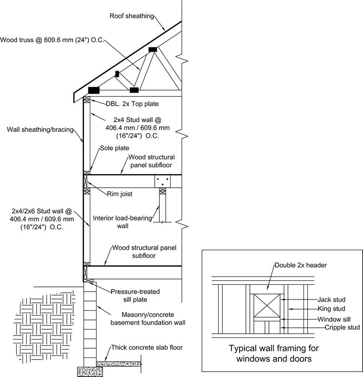
Figure ii.
Department view of typical residential wood-framed home. Note: in this figure, a small rectangle with 10 inside indicates the cantankerous section of forest member, and DBL stands for double.
As noted earlier, much of the woods-framed structural design tin can be achieved using design aids. The design professional person will typically use these pattern aids to the greatest extent possible and so perform structural analysis and design for any detail that is beyond the scope of the pattern aids. This is the arroyo that will be used for this study. The blueprint drawings are shown in the Appendix. The associated detailed calculation is not provided due to space limitation; only the necessary results volition be mentioned.
iv.1 External load transfer (load path)
External loads must be transmitted to footing through the structural system of the edifice. Two main systems are needed to accomplish this transfer properly: gravity system and the main air current force resisting arrangement (MWFRS). The gravity system transmits the vertical loads through a system of trusses, joists, and beams to foundation, which in turn transmits the load to ground, while the MWFRS transfers lateral current of air load to foundation through a organisation of shear walls and flexible diaphragms. It is important to recognize that the ground must be properly prepared and evaluated to ensure skilful load transfer. Typically, foundations are placed on virgin soil or engineered (compacted) make full. All organic materials should be removed along with excessive amounts of h2o.
four.2 Gravity organization design
The gravity system in this domicile starts at the roof and ends in the soil. Vertical loads must take a continuous path to the ground. Generally, the gravity system in this example consists of OSB sheathing, engineered roof trusses, load-begetting stud walls, dimensional lumber headers, engineered I-joist floor arrangement, engineered woods beams, structural steel girders, and a concrete foundation.
4.three Roof sheathing
The OSB roof sheathing, as illustrated in Effigy three, serves to transfer gravity load (i.due east., dead, live, and snow loads) and wind suction to roof framing members. The roof sheathing also transfers the lateral wind loading through diaphragm action to the structure. Attachment requirements of the capsule to roof trusses are governed by the greater of the current of air uplift force or the shear transfer requirement of the connection.
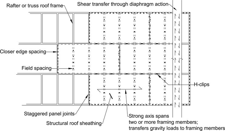
Effigy 3.
Roof sheathing illustration.
According to IRC Tabular array R503.2.1.i(one), eleven.i mm (7/sixteen inch) roof sheathing (24/xvi span rating) is acceptable for this case. The sheathing can be used with or without edge support at 609.6 mm (24 inch) spans with an allowable live load of 1.92 kN/m2 (xl lbf/ftii), and a total allowable load of two.39 kN/mii (50 lbf/ft2), which is less than the ane.44 kN/m2 (30 lbf/ftii) snowfall loading plus 0.57 kN/thouii (12 lbf/fttwo) roof expressionless load. Information technology may be possible to utilize 9.5 mm (iii/8 inch) sheathing, but 11.1 mm (vii/16 inch) thickness is more than readily available and common in the locale. In this example, the sheathing will be specified with panel border clip support. Co-ordinate to IRC Table R602.3(1), the sheathing is required to be attached to the truss framing with 63.v mm (2½ inch) 8D common nails spaced at 152.4 mm (6 inch) on center (O.C.) around the edges of the panel and 304.8 mm (12 inch) O.C. at intermediate supports (field). Notation that the gable finish sheathing connections must be spaced at 152.4 mm (vi inch) O.C. at both the perimeter and intermediate locations.
4.four Engineered roof trusses
Prefabricated trusses are intended to be used on this residence and required technology design by the manufacturer. Woods roof trusses must exist designed in accordance with IRC Section R802.10. A designer or architect volition typically draw the shape of the roof organisation, then the truss designer will design the truss system to fit the concept. Typically, it is the responsibility of the habitation designer to ensure that the gravity and lateral loads from the trusses are properly transferred to the wall below. This involves specifying the connectedness to wall system below. When the truss drawings are received by the home designer, the loads to the structure, based on the analysis conducted by the truss designer, are typically listed on the engineered truss plans. The designer would use these loads for design. For the example example presented here, however, a ready of detailed truss drawings are not available. The causeless loadings described earlier volition be used for design. This is typical of an initial home design. A designer will utilise their assumptions and then verify such assumptions when the final truss plans are received.
4.5 Exterior walls
The gravity load-bearing elements of the wall organization presented here are the 2 × 6 dimensional lumber studs and the elevation and bottom plates (or sole plate). See Figure two for the location of the elevation and bottom plates. The 2 × half-dozen designation refers to a woods framing member with a nominal l.viii mm (ii inch) width and a 152.four mm (6 inch) depth. The actual measurements of the fellow member are approximately 38.i mm (one½ inch) wide and 139.7 mm (5½ inch) deep. The pinnacle and bottom plates serve to transfer both gravity and lateral loads between floors. The meridian plate serves three purposes: (1) a chord for the MWFRS, (2) a strut betwixt shear panels in a wall line, and (three) a means to transfer gravity loads to the stud from the joists and trusses.
According to IRC Tabular array 602.three(5), 2 × six studs can be used at 609.6 mm (24 inch) O.C.; however, it is more typical for the studs to exist spaced at 406.4 mm (16 inch) O.C. The advantage of this is that when using a double 2 × 6 top plate, the joists or trusses that bear on the wall practice not have to bear direct on the stud. If using a single top plate or studs spaced at 609.vi mm (24 inch) O.C., and then the joists or trusses must either be straight above the stud or within 25.iv mm (1 inch) of the stud according to IRC Section R602.3.2. It is possible to use 2 × 4 studs spaced at 406.4 mm (16 inch) O.C., but this is not common because of the popularity of using fiberglass batts to encounter the International Free energy Conservation Code (IECC) [7] envelope insulation requirements. The connections between the studs and the plates are co-ordinate to IRC Tabular array 603.2(1). The connections are typically nails, and the nail sizes vary between 8D and 16D based on the item.
4.6 Headers within wall system
Structural header members are used to create openings in a load-bearing wall assembly for fenestration (windows and doors) as shown in Figure ii. Dimensional lumber headers are preferred by designers when loading is low. Often times when point loading is present on a header or spans are large, an engineered lumber header, such as an LVL, may go cost-effective. An instance of a typical LVL is shown in Effigy iv. LVLs are too ofttimes used in wall systems when smaller depth members are required due to space constraints.
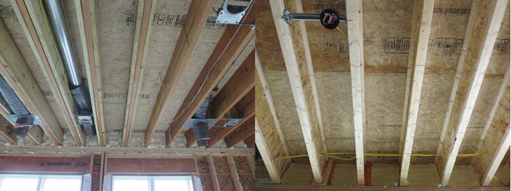
Effigy 4.
Typical I-joist and LVL (courtesy Timber Rock Homes).
When specifying headers, the designer may cull to specify larger headers in some locations for consistency sake. By minimizing the corporeality of different axle sizes on the plan, the designer reduces the risk of misplacement of headers. As in the instance of the roof sheathing, information technology may also turn out that some axle sizes may be more than readily available, and therefore larger sections may be more economic. For example, a ii-ply 2 × 8 beam, with a demand capacity ratio of 0.944 controlled by bearing, is adequate for BM3, merely because the entire back wall on the first floor is composed of two-ply ii × x headers and all the other headers in the building are 2 × six's, it makes sense just to specify a two-ply 2 × 10 beam for this location as well. This eliminates the need to have another beam size on site and provides for the opportunity to utilize trim pieces from a dissimilar header cutting to make up this short beam.
4.seven Above-course floor system
In this home design, an engineered floor organisation volition be used. Every bit shown in Figure 4, I-joists take become pop and price-constructive in the residential home construction market. I-joists have several advantages over dimensional lumber joists, ane of which is a greater span-to-depth ratio. This allows for shallower floor assemblies, longer spans, and higher ceilings. I-joists are generally more stable than dimensional lumber. This almost eliminates the need for bridging in a floor system and ensures consistency of engineering properties.
An I-joist floor organization is an engineered product. Typically, a designer will transport their floor plan along with preliminary input from the designer to the I-joist manufacturer. The manufacturer will then design the floor system co-ordinate to the requests of the homeowner and designer. Live load deflections are often limited to Fifty/480 (axle span/480). Because longer spans can be achieved past using an I-joist product, the chances of flooring vibration occurring increase, simply can be controlled, as designers volition often restrict deflection to L/480.
It is common for designers to use span tables to select an initial flooring joist size. This volition provide a fairly accurate estimate and let the designer to select a flooring associates depth. The improved stability and increased stiffness of I-joists allow designers to consider larger spacing for the flooring joists. Information technology is common to specify I-joists at 487.seven mm (xix.two inch) O.C., whereas it was mostly mutual in the by to specify dimensional lumber joists at 406.4 mm (16 inch). Additionally, lumber joists are only bachelor in certain lengths. This made the need for a splice at an internal bearing wall or beam a very mutual occurrence. The length of I-joists is more often than not only limited by transportation and site restrictions. An I-joist bundle will typically arrive at the site precut and ready to be installed with minimal modification.
As in the example of roof sheathing, flooring sheathing serves two purposes. Kickoff, it acts in the gravity organization to distribute floor loads to the joists. Secondly, it is the primary shear resisting component in the floor diaphragm, which will be discussed afterward. Typically, the gravity loads govern the thickness choice of subflooring, and the shear requirements dictate connection to joists [8].
In one case again IRC Table R503.ii.1.1(1) will be used to size the sheathing. In this instance, the sheathing will serve every bit both the underlayment and the subflooring. From the tabular array, either 18.3 mm (23/32 inch) or xix.ane mm (3/4 inch) tongue and groove oriented strand board (OSB) sheathing would be advisable, whichever is more cost-effective and readily available. It is possible that 15.1 mm (xix/32 inch) or 15.ix mm (5/8 inch) sheathing could exist used, but spans are restricted to 508 mm (20 inch). Although the joists will exist specified at 487.7 mm (19.2 inch), which is less than the limit, it is likely that at to the lowest degree a few joists within the floor system volition demand to be spaced greater than 508 mm (xx inch). An example is when joist bays are used for heating, ventilating, and air conditioning (HVAC) ductwork, the joists are often spread in those locations to 609.6 mm (24 inch). In this instance, the thinner sheathing would be inadequate. IRC Table 602.iii(1) specifies attachment of the sheathing to joists with a 50.8 mm (two inch) 6D deformed nail or a 63.5 mm (2½ inch) 8D mutual nails spaced at 152.4 mm (six inch) O.C. around sheathing edges and 304.8 mm (12 inch) O.C. for intermediate field spacing.
Joists for this project are selected from the Trus Joist #TJ4000 specifier'south guide [9]. From the span tables within the guide, TJI110 301.6 mm (11 7/8 inch) joists are adequate for both the first and 2d floors of this residence. The maximum span in the home is approximately 4.70 m (xv foot–5 inch). The TJI110 301.6 mm (xi seven/viii inch) joist tin bridge a maximum of iv.90 m (16 human foot–ane inch) because L/480 deflection limit, i.92 kN/10002 (40 lbf/ft2) alive load, and a 0.96 kN/thou2 (twenty lbf/ft2) dead load. The TJI 28.6 mm (1 i/8 inch) engineered rim board will be used for the perimeter of the flooring system. The rim board serves to transfer compressive and shear loads from the exterior walls in a higher place to foundation beneath. Information technology too acts to enclose the perimeter of the flooring organization. Typically, joists are toenailed to sill plates at ends and nailing plates at intermediate points. Metal hardware such as that made by USP [10] or Simpson Stiff Tie [xi] is used to brand whatsoever flush beam-to-beam or joist-to-beam connections within the floor system. An example would be the stair trimmer detail shown in Figure 5.
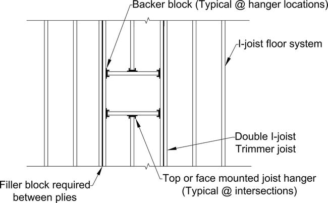
Figure 5.
Stair trimmer detail.
A double joist or LVL product can be used to function as stair trimmers in an engineered floor system. When loads are low, double joists are economical, simply every bit loading and span increase, an LVL is sometimes needed. LVLs are sometimes used because the installation is cleaner looking and easier to finish than double joists. Double joists often require padding at connections and sometimes begetting, which is ordinarily OSB, to compensate for the space between the web and flanges. LVLs are conveniently made in the aforementioned depths as I-joists, which makes it like shooting fish in a barrel to use within the floor systems.
A do good of using I-joists over dimensional lumber is that it is easier to put holes through the joists for mechanical runs. About I-joist manufacturers will have predetermined locations or precut holes in the joists where mechanical penetrations are anticipated. Some guidance is typically specified in the manufacturer literature. Holes in dimensional lumber typically crave structural analysis and stress evaluation as they become big relative to the depth of the joist or beam.
iv.viii Girder sizing
For this example habitation blueprint, a key steel girder will be used to collect the flooring loads and transfer to pad footings in the heart of the basement. Information technology is common for designers to use either steel girders or manufactured lumber girders in homes today. These types of girders are much stronger than dimensional lumber beams and are necessary in many instances because of the longer commanded engineered I-joist spans and homeowner request for open basement floor plans. Both manufactured lumber girders and steel girders must be either specified or the design reviewed by a professional engineer.
Steel girders are often called over manufactured lumber girders when girder spans are long, caput room in the basement is a premium, or steel is readily available. For this particular builder, the head room in the basement is important because they similar to advertise their homes with basements that can be finished in the time to come. A W8x18 girder works well for them considering it's a shallow beam and the flange width is small enough that the beam can fit in a ii × half dozen wall making the girder unnoticeable if the basement is ever finished.
A W8x18 steel girder, with a design moment chapters of 86.v kN-m (63.8 kip-ft), is more than adequate to resist the internal moment of 31.5 kN-m (23.2 kip-ft) for the controlling load case. Information technology is possible that a smaller girder could have been used, but W8x18 is the minimum size the architect will utilize. Small sizes tend to have stability issues and can be susceptible to local buckling problems acquired by larger point loads. In addition, this is a readily available steel section from the builder's steel supplier.
The design of residential girders involves assumptions regarding the bracing of the beam. The American Institute of Steel Construction (
Steel girders in well-nigh residential cases are ordinarily ordered in a single length if possible to avert splices and therefore are continuous over their intermediate supports. Negative moment occurs at the intermediate supports, which puts the lesser flanges in compression in those regions.
If information technology is assumed that the columns practise not provide adequate bottom flange back up, then these negative moment regions would be destabilizing, and since inflection points are not typically recognized every bit a brace indicate (SCM Appendix 6.3), the unbraced length would have to be taken equally the entire axle length of 11.0 grand (36 anxiety), which would require a very large department. Additionally, if no compression flange bracing is assumed at the supports, then the beam fails the concentrated load check in SCM J10.iv for web sidesway buckling. Section J10.4 requires the supports to be adequately braced under these circumstances.
If information technology is assumed that the column is braced against rotation at the supports by either assuming the column connection is acceptable or providing additional bottom flange support, then the unbraced length reduces to the distance between the columns, which in this case is nine′-0″ and the beam passes both strength and full-bodied load checks.
Likewise restraint against rotation should be provided at the ends of the beams, which are seated in the axle pockets. Typically, axle pockets in the physical wall are oversized to facilitate easy installation of the beams. This creates the opportunity for twisting. SCM Section J10.seven requires all unframed girder ends to have a pair of transverse stiffeners if unrestrained. In this case, a better idea would be to grout the pocket equally shown in Figure 6, or provide some blazon of shim, later installation to restrain the end against rotation. It should exist noted that the required moisture direction and thermal envelope components are non shown for clarity in the figure.
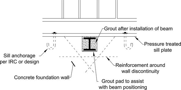
Effigy 6.
Steel girder beam pocket detailing.
Another consideration for girder sizing is live load blueprint loading. Since the girder is a continuous beam having multiple spans, ASCE 7 Section 4.3.iii requires the consideration of design loading. In this case, information technology turns out that applying live loading to spans 1, 2, and 4 only produced the largest internal moment of 31.five kN-m (23.three kip-ft) in the beam. Figure 7 shows the moment diagram for the controlling load combination and the spans that were loaded to produce it.

Effigy 7.
Moment diagram showing maximum internal moment over support 2.
Pattern loads are considered in the structural analysis software bundle Enercalc that was used for beam pattern. Enercalc runs all permutations of live load application and reports the worst-instance scenario in envelope format. Data for individual permutations is not able to be extracted. For this instance, a separate bank check was made using Computers and Structures, Inc. (CSI) SAP2000 finite element modeling software to verify the results of Enercalc and decide the controlling permutation. Results were within i% of each other betwixt the ii analysis packages.
Design loading was pregnant in this example. If just the full intensity alive load application was to be considered, then the design moment would accept been underestimated by approximately 5%, and the support reactions would have been underestimated by approximately 5% at supports two, 4, and 12% at support 3. If ignored, this could have led to the undersizing of both adjustable column and pad footing.
4.nine Adjustable columns
Adaptable columns are generally used in residential construction as intermediate supports for basement girders. Adaptable columns are readily bachelor at almost whatever hardware stores and can be adapted in height to lucifer site weather condition by the contractor. Figure viii shows an instance of typical adjustable columns. The maximum loading, as reported past the manufacturer, is a factored allowable ASD load capacity (Ra). Reactions determined by ASD load combination can exist used to direct size the column from the manufacturers testing data. For this particular home design case, the maximum ASD girder reaction is 80.5 kN (18.i kip). According to the manufacturers data, an 88.9-mm (3½ inch) and two.31-mm-thick (11 gauge) column with a meridian between two.21 m (7 foot–3 inch) and 2.31 chiliad (7 pes–7 inch) has an allowable load of 95.6 kN (21.5 kip), which is greater than the maximum column axial demand of 80.v kN (18.1 kip). All three columns volition be specified for this maximum loading. This volition subtract the chances of misplacing columns.

Figure viii.
Typical adjustable column.
4.10 Foundation design
A combination of components are used to transfer load from the to a higher place-grade portion of the home to the ground. In this home, concrete walls supported past concrete strip footings are used to support the exterior walls and resist lateral earth pressure. Interior loads are transferred by the intermediate girder through columns to concrete pad footings. It is common practice in residential design to specify the foundation walls prescriptively but design the footings. This is the approach that is taken for this written report. The American Physical Institute (ACI) 332-08 [thirteen] and ACI 318-xiv [xiv] are used as references for this design. These documents are adopted by the 2015 IRC and often lead to more than economic designs when compared to the requirements of the IRC.
4.11 Foundation walls
Based on soil categorization, the ACI provides prescriptive foundation sizing tables in Appendix A of ACI 332, which are ordinarily appropriate for most situations. For most residential designs, geotechnical exploration and lab testing are cost prohibitive, and therefore soil pressures must be causeless. ASCE 7 provides design lateral soil load that can exist used in the absenteeism of site-specific geotechnical information.
For this design, the equivalent soil pressure will be estimated at ii.xv kn/m2 per linear meter (45 lbf/ftii per linear foot). According to ASCE 7 Table iii.2.1, this is representative of a type GC soil (unified soil nomenclature), which is described every bit a clayey gravel, poorly graded, gravel, and sand mix. Assuming horizontal backfill and a vertical foundation wall, this is roughly equivalent to 19.6 kN/one thousand3 (125 lbf/ftthree) soil with an internal friction bending of 28 degrees [fifteen].
According to ACI 332 Tabular array ix, 21 MPa (3000 psi) is the minimum required compressive forcefulness for foundation walls in the severe weather condition probability category. Considering the physical will be exposed to weathering, it must exist air entrained, having an air content of 6% plus or minus 1.5%.
| Walls | Length required | Length provided | Method |
|---|---|---|---|
| First floor | |||
| Due north | 4.24 (167) | 8.23 (324) | CS-WSP |
| Due south | 3.40 (134) | iii.66 (144) | WSP |
| East | 3.20 (126) | iii.66 (144)a | WSP |
| W | 3.twenty (126) | 3.66 (144) | WSP |
| Second floor | |||
| N | 1.83 (72) | 2.44 (96) | WSP |
| South | 1.83 (72) | 2.44 (96) | WSP |
| East | 1.52 (60) | iii.66 (144) | WSP |
| West | 1.52 (60) | iii.66 (144) | WSP |
| Garageb | |||
| North | one.27 (fifty) | ii.44 (96) | WSP |
| E | ane.32 (52) | one.37 (54) | WSP |
| W | 1.32 (52) | 2.44 (96) | WSP |
Tabular array 9.
Wall bracing. Values in meters (inches).
For WSP methods panel lengths between 0.914 and 1.22 m (36 and 48 inches) are allowed just must exist adjusted per IRC Table 602.10.three.
The required bracing for the garage/main business firm common wall will be added directly to the first floor n wall.
The concrete foundation wall for the master construction in this example has an unsupported height of 2.44 m (8 foot) and volition be subjected to approximately ii.13 yard (vii pes) of unsupported backfill when in service (Figure 9a). For this state of affairs, considering reinforcing confined with a yield strength of 420 MPa (lx,000 psi), ACI 332 Table A.four allows for the apply of a plain physical (no vertical reinforcing needed) 203.2 mm (8-inch)-thick foundation wall. To minimize shrinkage peachy, all the same, ACI 332 requires the apply of three continuous horizontal bars in the wall. One must exist placed within 609.6 mm (24 inch) of the meridian, one within 609.6 mm (24 inch) of the bottom, and the terminal ane in between the other two. ACI 332 likewise prescribes 12.7 mm bore (½ inch) dowel rods at a maximum of 609.6 mm (24 inch) O.C. or a keyway to be provided in this instance since unbalanced backfill pinnacle exceeds i.22 m (four pes).
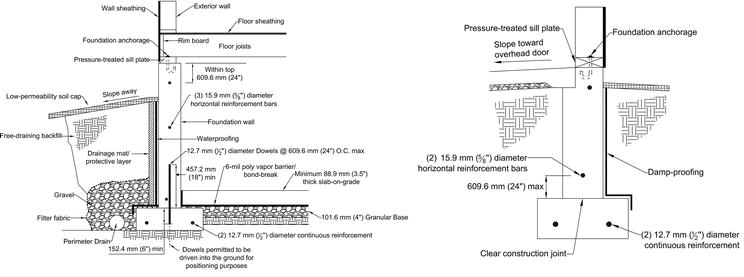
Figure 9.
(a) Typical basement wall and (b) typical garage frost wall.
The garage wall foundation walls are all 0.91 m (3 feet) in height and accept no unbalanced backfill. According to ACI 332, 203.2 mm (viii inch) plain concrete walls are adequate. No vertical reinforcing is necessary, but horizontal reinforcing is still required (Figure 9b). The wall height is less than one.83 m (6 feet), which requires only 2 12.seven mm diameter (½ inch) reinforcing confined, 1 within the tiptop 609.6 mm (24 inch) of the wall height and the other inside the bottom 609.vi mm (24 inch) of the wall top. Considering the unbalanced backfill is less than 1.22 m (4 anxiety), Department 6.3.4 allows for the apply of a clean construction joint versus dowel rods.
four.12 Wall strip footings
Continuous strip footings will be used to support the exterior foundation walls. The wall footings will be designed (as opposed to prescriptive). No soil testing data is bachelor, and then the IRC minimum of 71.8 kN/g2 (1500 lbf/fttwo) prescribed in Table R401.four.1 will be used for pattern. The assumption will exist made that the footings are not exposed to weathering; therefore, ACI 332 prescribes 17 MPa (2500 psi) minimum compressive strength for the concrete.
For this case, it volition be assumed that the load from the exterior wall will deed concentrically on the footing. In other words, the footings will be designed for uniform pressure simply, and no imbalanced soil pressure due to the presence of a moment will be considered. This is a reasonable assumption considering basement walls are typically restrained from translation at the top and bottom by the first floor assembly and the basement slab, respectively. The presence of this restraint allows walls to be designed as a vertical beam with pinned ends (no moment transfer). In addition, the opposing soil exterior lateral loading tends to beginning the pocket-size amounts of eccentricity created by in a higher place-grade wall offsets, so in do the effects of above-class wall offsets are more often than not ignored for wall basis design. Effigy 10 shows an illustration of the analytical model for a typical residential basement wall.

Figure 10.
Free body diagram of a basement wall. Annotation: the arrows show loads, and small rectangle with x inside indicates the cross section of woods fellow member.
Residential wall footings are typically specified in depths of 152.iv mm (6 inch), 203.2 mm (8 inch), or 254 mm (10 inch), and widths are mostly varied in 50.8 mm (2 inch), 76.2 mm (three inch), or 152.four mm (6 inch) increments. Both the IRC and ACI 332 let for the use of 152.iv mm (6-inch)-thick footings (assuming adequate strength), but the developer in this case prefers to employ 203.two mm (8-inch)-thick footings. This allows for some boosted safety precaution when manifestly concrete footings are used. When specifying footing widths, this detail developer prefers to utilise even dimensions in 50.8 mm (2 inch) increments.
In this instance, the wall footing design is split into 3 segments, the main load-bearing walls of the east and westward (perpendicular to joist and truss spans), the gable end walls, and the garage walls. Wall footings were designed as plain concrete strip footings according to the requirements of ACI 318, considering the increased modulus of rupture immune by ACI 332 Chapter 7. Soil bearing force per unit area controlled all designs. With a soil bearing pressure of approximately 67 kN/m2 (1400 lbf/ft2), the begetting walls required 203.two × 457.2 mm (8 inch by 18 inch) footings. The gable end wall footings and garage footing were able to be reduced to 203.two × 406.four mm (8 inch past sixteen inch). The wall region beneath the supporting columns for the garage door header controlled the design. Considering ASD load combination 4 and a point load distribution angle of 45 degrees within the physical wall, the soil pressure level beneath the column would be approximately 67 kN/m2 (1400 lbf/ft2) besides.
The footings were designed as patently concrete footings. Patently physical footings are the most economical because of the absenteeism of the steel reinforcing cost. Some developers are comfy relying on the unreinforced concrete footing to maintain its integrity over the service life of the building, but some adopt to add light reinforcing to assist preclude groovy due to unexpected soil discontinuities. ACI 332 Department 6.2.4.1 prescribes the utilize of ii 12.7 mm bore (½ inch) confined for locations with discontinuities less than 914.four mm (36 inch) in length.
four.xiii Isolated pad footings
Isolated pad footings are typically used to transfer vertical gravity load from interior columns in the basement. In this example, there are iii pad footings required to support the interior central steel girder. Interior pad footings are not subjected to weathering, so 17 MPa (2500 psi) concrete compressive force is adequate. The default value of 71.eight kN/g2 (1500 lbf/ft2) is used for the soil bearing capacity, as in the strip footing design.
Reinforced square concrete footings were selected as appropriate for this application. Plain physical pad footings are sometimes adequate for smaller footings with programme dimension of 609.6 mm (24 inch) or 762 mm (30 inch) square but typically require reinforcement equally the plan dimensions of the footing increases. In this case, 3 1219.2 mm (4 foot) square footings using iv 15.9 mm (5/eight inch) bore bars in each directions were required. Because LRFD combination two, two-mode shear (punching shear) with a need/capacity ratio of 1.30 was the controlling failure mechanism for the concrete footing and required an increase in footing depth from 203.2 mm (8 inch) to 254 mm (x inch). This reduced the demand/chapters ratio to the acceptable level of 0.698.
4.xiv MWFRS design
The typical residential MWFRS arrangement is composed of a system of flexible diaphragms and shear walls. Every bit shown in Effigy 11a, wind load is transferred from exterior walls perpendicular to the wind direction to structural forest panels, typically OSB or plywood, fastened to roof or floor framing. The flexible roof or floor diaphragms, as shown in Figure 11b, deed like to a deep beam and distribute the wind load as reactions to the exterior walls parallel to the wind loading (Figure 11c) and distribute to the potent structural shear panels within those walls past direct diaphragm connexion or strutting.
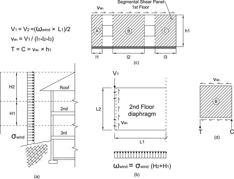
Figure 11.
(a) Wind pressure distributed through external walls to flexible diaphragm. (b) Flexible diaphragm distributes load to parallel walls. (c) An case of a segmental shear wall load distribution approach. (d) Shear wall segment resolution of overturning forces. Note: in this figure, the following notation is used: Five for shear strength, T for tension force, C for compression forcefulness, fifty and 50 for Span length, h and H for height, σ for current of air pressure, ω for wind load per unit length, and Vw for shear per unit of measurement length.
The structural wall panels, as shown in Figure 11d, provide the necessary shear resistance and transmit the loads vertically (overturning tension and compression loads at the corners of each structural panel) to the foundation though a system of hold-downs and connections.
Typically, the panels are specified past design aids such as the IRC or the Wood Frame Construction Manual (WFCM). When using the IRC approach, the prescribed nailed connections are assumed to exist adequate to transfer the overturning shear forces shown in Figure 11 to the foundation. If an engineered pattern or the WFCM prescriptive approach is used to specify shear wall panels, then structural connectors must be specified to transfer these overturning forces. The connection system must have an identifiable load path to the foundation. For this reason, most residential designers utilize the IRC to specify shear panels and their fastening system. When using a wood truss organisation as office of the roof diaphragm, such as the one in this domicile design instance, structural connectors are typically specified to transfer the horizontal shear loads and uplift loads resulting from the roof wind loading.
The loads from the shear wall panels and flooring diaphragm are transferred to the sole plate past nailed connections and sometimes structural connectors if necessary. The sole plate is fastened to the foundation wall with cast-in-place anchors such as J-bolts or post-installed anchorage that must be drilled after the physical has had time to cure, such every bit expansion anchors, epoxy anchorage, or screw type. With a prescriptive approach, the prescribed anchor bolts are assumed to adequately transfer both the overturning actions and horizontal deportment generated past the wind.
iv.15 Overturning and sliding assay
It's mostly good exercise to review the whole construction for stability under wind loading and so blueprint the individual components of the lateral strength resisting system as required. An overturning and sliding analysis is conducted to determine the required strength of the connections between main assemblies such as the roof-to-wall connections, floor-to-wall connections, and the above-form building-to-foundation connections.
Many times, homes have attached garages where the garage is not integral to the primary living space, such as the one in this example. The garage and the main edifice can exist somewhat treated as dissever buildings for the purposes of MWFRS pattern. The garage can sometimes help resist main building current of air loading every bit long as the wall offsets are not too large; otherwise they must be treated completely separately as far as wall bracing goes. In the east-west direction, the common northward wall between the garage and the main structure is generally treated as an outside wall, and bracing will exist prescriptively specified as such, which will act to transfer load from both the garage and the main building.
ASCE 7 Effigy 28.vi.1 cases A and B were used to determine the magnitude of current of air forces practical to the building. The magnitudes of the loads were reported previously in Tables vi and 7. The load effects created by the external wind forces were used to specify the hold-downs and shear connectors necessary to maintain continuity of MWFRS load path. The garage was not analyzed, just the procedure would be the aforementioned. To simplify the analysis, the terminate zone loads for instance A were practical on both ends to simplify the assay. To maintain a uniform counterbalanced load in case B (wind applied to the gable terminate), a weighted average of 0.69 kN/grand2 (14.4 lbf/ft2) was taken for zones A and C and applied horizontally. An boilerplate of zones E and F that was calculated to be −0.95 kN/m2 (−19.eight lbf/fttwo) was applied vertically to the windward side of the roof, and an boilerplate of zones G and H that was calculated to be 0.61 kN/grandtwo (12.seven lbf/ft2) was practical vertically on the leeward side of the roof.
Analysis showed that structural connectors were needed for the roof, but non for the floor-to-floor connections and the foundation connectedness. Connectors for the truss ends must be able to simultaneously transfer uplift and north-due south shear loading also as shear loading alone in the east-west management. Simpson Strong Necktie (SST) H2.5A hurricane connectors were considered for the truss end-to-meridian plate connexion. This connection resists both shear and uplift. The H2.5A has a shear capacity of 0.58 kN (130 lbf) and uplift capacity of 1.62 kN (365 lbf). The truss finish loads are, respectively, 0.18 kN (twoscore lbf) and 0.27 kN (60 lbf). Applying a unity equation, the need/capacity ratio is 0.18 kN/0.58 kN + 0.27 kN/ane.62 kN = 0.477 < 1.0; therefore, the connector is acceptable. An example of a typical truss connector is shown in Figure 12. SST A21 angles were considered for the gable end truss-to-top plate connection. This connection is subject to a total shear load of ten.7 kN (2400 lbf) when the current of air is practical perpendicular to the gable cease. SST A21 has a blueprint capacity of one.09 kN (245 lbf) per connector; therefore, the required number of connectors will be x.7 kN/one.09 kN, which gives approximately 10 connectors.

Figure 12.
Typical truss-to-superlative plate structural connector.
The structure was checked for overturning at the second floor and at the starting time floor. The weight of the construction was adequate to resist the overturning moment in both locations. Sliding was only checked on the roof to specify the structural connectors. Sliding on the 2nd floor is resisted by the nailed connection between the bottom plate and the floor assembly. Typically, there are sufficient nails engaged to resist the shear forcefulness. As for the building-to-foundation connection, there is no reason to await an extraordinary loading at this junction, then anchor bolts are specified according to IRC Chapter R403.1.6. The I-joist to soleplate toenail connection was not checked in this assay but should be checked in an bodily design.
iv.16 Wall bracing
Wall bracing for residential construction typically involves designating sections forth the exterior wall length as shear panels. Structural wood panels are used on the exterior side of the wood framing, and gypsum wallboard on the interior provides the shear resistance and load transfer capability. Plywood or OSB is typically used for the wood structural panels. IRC Tabular array 602.3(3) prescribes a ix.5 mm (3/viii inch) minimum structural panel thickness for 406.4 mm (16 inch) O.C. stud spacing; withal, the architect prefers a 11.i mm (vii/16-inch)-thick OSB console, which is required to be fastened to framing using 8D common nails at 152.4 (half dozen inch) O.C. around the perimeter and 304.8 mm (12 inch) O.C. in the field.
IRC Section R602.x will be used to specify shear panel length and location along the wall line. Section R602.x has provisions for diverse wall bracing methods. The bracing in this domicile volition follow the requirements for the intermittent woods structural panel (WSP) method or one of the continuous sheathing methods. Considering this home is categorized in seismic design category A, Department 602.10.1 allows for different methods to be used along dissimilar wall lines. Different intermittent methods could even be used along the same wall line in this category, simply if using whatever of the continuous sheathing methods, the whole wall line must exist continuously sheathed.
For the design of this home, it was more economical to utilize the WSP method for the majority of the shear panels. Department R602.ten requires 609.6 mm (24 inch) corner returns or braced panels at the stop of each wall. At least one of the corners does non run into this benchmark. When this occurs and the designer is using the continuously sheathed wood structural panel (CS-WSP) method, Section 602.10.4.iv requires the utilize of 3.56 kN (800 lbf) hold-down devices in lieu of a 2 foot corner render. This is often costlier than the extra amount of capsule required for the WSP method. Some other result to consider when specifying wall bracing is the stud spacing. In this home, the studs are spaced at 406.4 mm (16 inch O.C.); therefore, it is prudent to specify shear panels 406.4 mm (16 inch) increments, fifty-fifty though the requirements may exist less. The location of the shear panels is specified in the drawing prepare located in Appendix A.
4.17 Horizontal floor diaphragms
The floor assembly is treated as a flexible diaphragm when transferring lateral loading. Wind is transferred from a tributary area of the exterior wall to the rim lath of the flooring associates and then into the structural sheathing. The floor sheathing then transfers that load to the exterior shear walls (structural panels within the wall arrangement) parallel to the wind direction beneath the floor assembly. The diaphragm is treated like a deep beam for the purposes of assay. The reactions are the connections with wall below. The floor assembly deflects, which causes tension and compression forces called chord forces in the walls below, which are perpendicular to the wind loading. The sheathing layout and the zipper of the sheathing to the I-joists have the greatest effect on the forcefulness of the diaphragm. In this case, the floor sheathing and the required nailing were specified from the IRC in the floor associates department of this written report.
iv.xviii Connections
Most connections in wood-framed homes are made up of nailed connections. The majority of the connections in a typical domicile can be found in IRC Table R602.iii. The items specified from the IRC in this woods-framed section are based on compliance with this tabular array. In this study, but a few of the typical disquisitional connections for the structural system were specified.
Advertisement
5. Concluding remarks
This chapter presented a consummate design of a typical United states of america single-family unit home made of conventional woods-frame organisation. Initially, the applicable building and material codes were introduced and relevant provisions discussed. A typical home plan by a PA builder was discussed and explained for detailed blueprint. The process of load selection and load path and load combination was discussed. Then based on application of the resultant loads on typical structural elements, detailed designs for roof capsule, roof trusses, exterior walls, main wind force resisting system, floor system, girders, columns, and foundation walls and footings were presented and discussed. Where advisable, tips and guidelines for typical blueprint were offered then that the procedure presented can exist followed by designers as advisable. While other structural systems are becoming increasingly available, the woods-frame system is even so the dominating system equally in the USA lumber is readily available at highly competitive process. This makes structural systems other than conventional wood-frame less competitive, unless there are special weather where cost may not be the principal determining cistron.
References
- 1.
ICC (International Code Council, Inc.). In: 2015 International Residential Code for Ane- and Two-Family Dwellings; Country Guild Hills, IL. 2014 - two.
Rutkowski H. ACCA (Air-conditioning Contractors of America). Manual J Residential Load Calculation. eighth ed. Arlington, VA: Air conditioning Contractors of America; 2015 - 3.
ICC (International Code Coucil, Inc.). In: 2015 International Building Lawmaking; State Club Hills, IL. 2014 - 4.
ASCE (American Society of Civil Engineers). Minimum Design Loads for Buildings and Other Structures. Reston, VA: ASCE seven-ten; 2010 - 5.
AWC (American Wood Council). Wood Frame Construction Manual (WFCM) for Ane- and Two-Family unit Dwellings 2015 Edition. ANCI/AWC WFCM-2015; Leesburg, VA. 2014 - 6.
NAHB Research Eye. Inc. HUD (U.S. Section of Housing and Urban Development). Residential Structural Pattern Guide. Washington, D.C.: PD&R - U.S. Department of Housing and Urban Development; 2000 - 7.
ICC (International Code Coucil, Inc.). 2015 International Energy Conservation Code; State Club Hills, IL: International Lawmaking Council, Inc.; 2014 - 8.
Breyer DE, Fridley KJ, Pollock DG Jr. Design of Forest Structures—ASD. New York, NY: McGraw-Hill; 2003 - ix.
Weyerhaeuser. Trus Joist TJI 110, TJI210, TJI230, TJI360, TJI560 and TJI560D Joists Specifier'southward Guide,#TJ-4000; Seattle, WA. 2018 - 10.
Mitek Industries, Inc. USP Production Catalog 59th Edition,#2515; Minneapolis, MN. 2018 - eleven.
Simpson Strong-Tie, Inc. Forest Construction Connectors 2019-2020, C-C-2019; Pleasanton, CA. 2019 - 12.
AISC (American Institute of Steel Construction). Steel Construction Transmission. 14th ed. Chicago, IL: American Plant of Steel Construction; 2011 - 13.
ACI (American Concrete Institute) Committee 332. Code Requirements for Requirements for Residential Concrete and Commentary. ACI 332-08; Farmington Hills, MI. 2008 - xiv.
ACI (American Concrete Found) Committee 318. Building Lawmaking Requirements for Structural Physical and Commentary. ACI 318-fourteen; Farmington Hills, MI. 2014 - xv.
Lindeburg MR. Civil Engineering Reference Manual. 11th ed. Belmont, CA: Professional person Publications, Inc; 2008
Submitted: September 19th, 2018 Reviewed: March 18th, 2019 Published: May 11th, 2019
© 2019 The Author(southward). Licensee IntechOpen. This chapter is distributed under the terms of the Creative Eatables Attribution 3.0 License, which permits unrestricted use, distribution, and reproduction in any medium, provided the original work is properly cited.
Source: https://www.intechopen.com/chapters/67068
0 Response to "1995 Wood Frame Construction Manual for One- and Two-family Dwellings"
Post a Comment